 |
DATAKIT SDK
V2026.4
|


|
|
DATAKIT SDK
V2026.4
|
|
After enabling readers you want to use, then starting the Dtk_API, you must call the Dtk_API::OpenDocument() method to get a Dtk_MainDoc.
It contains a root Dtk_Component representing the assembly tree.
This step typically allows you to retrieve all information needed to build a BOM.
Generally, all part-level data (geometries, PMIs...) are available at Prototype component level.
Here is a sample model and its corresponding representation in Dtk_Component :
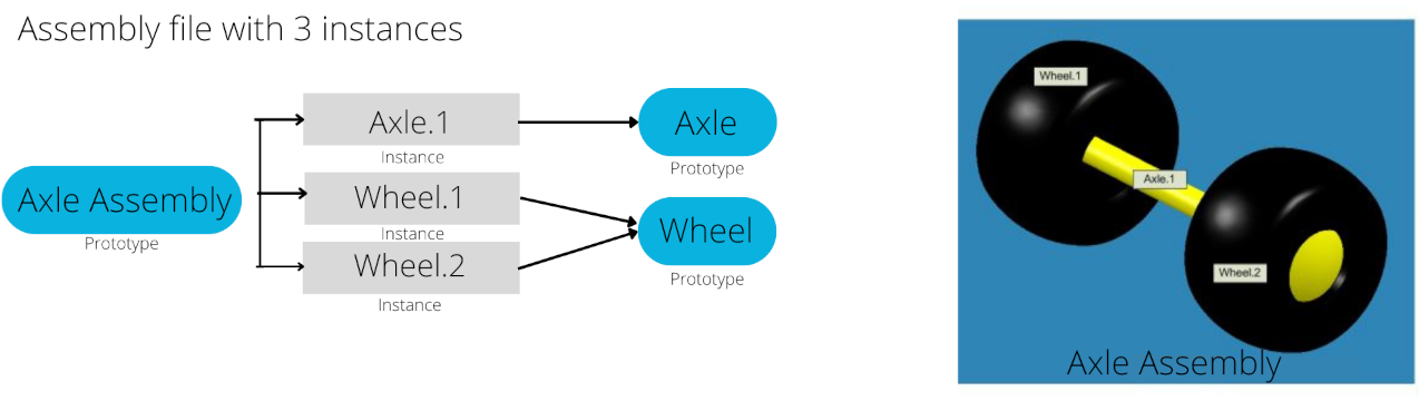
Some components may be artificially added at an assembly level, depending on CAD abilities and datakit support :
Parts within an assembly can be linked through Dtk_Constraint (contacts and positions).
Depending on the CAD format, you may retrieve additional cache data :
Dtk_API contains a file search engine to set your preferences for searching for files that are part of an assembly : Search File Engine Each Dtk_Component has a type, a name and children.
It can also have specific attributes like color, layer, visibility and metadata, all gathered in a Dtk_Info object.
Graphical attributes might be stacked across the component tree and have inheritance rules (see Using attributes across the Assembly Tree)
There are 4 different component types :
A Catalog component is a top-level component that may be the entry point for :
Dtk_MainDoc::IsMultiModel() returns DTK_TRUE The default catalog entry is what is shown in the original CAD software when opening the file.
It is given by method Dtk_Component::GetDefaultChildInCatalog().
A Prototype component represents a model that can have 0 or several children.
It must be referenced by an Instance component or a Catalog component (except if it is root).
From Dtk_Component you have to call Dtk_API::ReadComponent to get corresponding construction tree.
This will lead to the part-level definitions (see Handle Construction Tree).
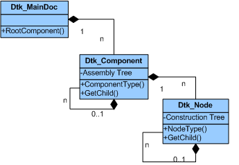
An Instance component has only one child which is the Prototype component and a placement matrix.
It can be referenced itself by a Instance component.
A Virtual component is an auxiliary component used to possibly gather other component types, or to add extra information.
It might not actually match a component from the original CAD model.
At an assembly level, some attributes can be stacked across the children tree.
In this case, a few general rules need to be observed when dealing with e.g. colors and visibilities :
Dtk_Component colors should prevail on any other defined colors
A single blue cube could be instantiated as green and red :
Dtk_Node). At screen, you'll see one red cube and one green cube.
The same kind of rules apply for visibility attribute.
Some formats allow both graphical and semantic representation.
If you need only data for visualisation you can :
Dtk_API::OpenDocumentGraphic() to get a Dtk_MainDoc object thenDtk_API::ReadComponentGraphic() on the Dtk_Component.This method gives you a set of meshes for 3D files and a set of drawing for 2D files.
Not all files contains such information so result may be empty. In this case you have to :
Dtk_API::ReadComponent() to get all data as semantics and browse the different node types.