- Join our Team
- Resources
-
Account
- |
- Cart
- EN FR
Weight watchers welcome a new fast, precise flawless STL !

July 01, 06
STL, the precursor of the world’s streamlined data formats, was created in 1990 by 3DS, the leading rapid prototyping vendor. It’s underlying principle is to represent geometry by a mesh of triangles. Easy to manage, generate and deploy, the format has since been adopted by all the makers of this type of machine, and also by developers of viewers that use STL files.
Though the format has always been easy to use, it has disadvantages, notably as data is notoriously faulty and imprecise. Hence, software developers are now turning away from STL to look more and more at compressed native formats. Building on its existing offerings in this area, Datakit has for several years been committed to finding ways to get round these precision and topology issues frequently encountered in STL. Its team has been collaborating closely with a specialist of tessellation, who is also a member of the Model Quality Commission at MICADO, France’s leading CAD industry association. The result is an efficient STL format, irrespective of the actual quality of the CAD source model.

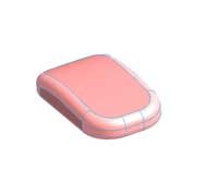
Brep Representation

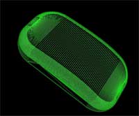
STL file : Tolerance = 0.1 Ratio above triangles = 2 maximum

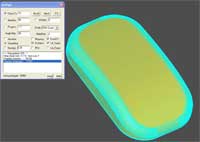
STL file : Same Tolerance but no triangles constraint
To avoid the numerous glitches that generally creep into CAD models, such as narrow gaps between surfaces, overlapping faces, faults in topological information and non-compliant parameter definitions …, and produce watertight triangulation and guaranteed precision, the models concerned (parts or assembles) are subjected to a rigorous analysis.
The first step consists of creating efficient discrete geometry so that each face of the model can then be cleaned up and its topology reconstituted robustly and efficiently. This essentially involves checking faces one by one and, if necessary, rectifying the border curves, the outer and inner contours of the faces to eliminate or rework features that are insignificant, non-homogenous, incoherent or badly defined … The analysis of the connectivity between faces serves as a basis for an iterative rebuilding of an assembly to within a user-defined tolerance.
Hanging and multiple edges are highlighted. Once these defects have been eliminated, the analysis can continue to solve problems of complex topology (non “manifold”) like those encountered in models used to simulate mould filling, for which it is imperative to detect the characteristic lines that form the boundaries or skin of each volume.
This method ensures that all the triangles in the mesh fit together perfectly. The mesh quality is largely determined by the user-defined chord deviation parameter or by other criteria such as the maximum size of the sides or the maximum ratio between the longest and shortest sides of the triangles (aspect ratio). Once the mesh has been rebuilt and after a final check for consistency, triangulation will be exported in the form needed by the downstream application.
Francis Cadin, Datakit CEO, explains: “Providing clean models is one of the keys to turning out high-quality prototypes. Calculation speed is also decisive for developers of viewer software who attach considerable importance to the speed at which models are read, whether to display or manipulate them or to rapidly integrate 3D views into technical documentation. We also give them the chance to import PLM information (such as properties, for example) in addition to the pure CAD data.”

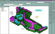
SMIRTware Inc., part of the Vero International Software group, has developed software for viewing dies and tooling, and holds an industry leading position in this sector. SMIRTware integrates the complete Datakit solution for importing native Catia V4, V5 and Unigraphics models that are corrected and then transformed into STL files. These files are then viewed within SMIRTDieShop™ and SMIRTDieNc™. Gilles Pic, Datakit’s correspondent at SMIRTware, explains: “like most representations of dies and tooling, these files are generally complex and cumbersome. In addition to the speed at which the 3D models are processed, we also have to allow users to define cross-sections, and this can only be done if the file quality is there. We also want them to be able to produce 2D annotations, and that is not always easy either.”
