 |
DATAKIT SDK
V2026.3
|


|
|
DATAKIT SDK
V2026.3
|
|
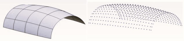
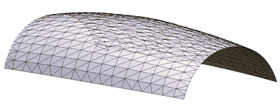
The Tessellation Library allows you to to convert a CAD model to a mesh (a set of triangles). A mesh can be usefull for graphic display or mesh based files generation (like OBJ, VRML, PDF-3D, CGR...).
Tesselation module should be used in datakit API context, i.e the function Dtk_API::StartAPI() should be called before any tesselation routine calls.
Our tesselation algorithm works roughly in 5 steps.
Dtk_mesh. 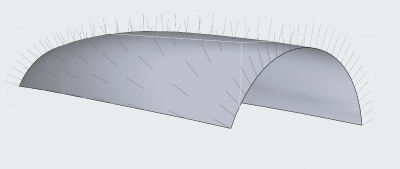
Dtk_mesh_face. 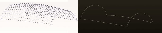
Dtk_Body, Dtk_Shell or a Dtk_Face, see How to tesselate each entity . tess_EndTesselation() to deallocate memory. To tesselate a Dtk_Body use tess_BodyToMeshes(). This method returns an array with one mesh per shell contained in the body.
To tesselate a Dtk_Shell use tess_ShellToMesh(). This is usefull to tesselate a body shell per shell. This method is used if you check if the shell is closed or not and you can ajust the result.
To tesselate a Dtk_Face use tess_FaceToMesh(). This is usefull to tesselate a shell face per face. In this case you cannot obtain any connexion beetwen faces.
To tesselate a set of Dtk_Face use tess_FacesArrayToMesh(). This is usefull to store each faces of a body in an array, and tessellate in one pass. This method can be used with surface format where each open shell contain only one face.
You can save an array with Dtk_Face entity , or use the structure Dtk_OrientedFaceStr , that store orientation in addition of face from shell.
A mesh is by definition less precise than its corresponding brep: a surface composed of a triangle set cannot be as "smooth" as its NURBS mathematical definition. Our tesselation module allows you to control this precision with a linear or angular tolerance.
Linear Tolerance
The linear tolerance represents the chordal error, i.e the maximum distance between the reference curve (the brep curve stored in the body) and the approximated mesh. A smaller value produces a denser mesh on curved geometry that is more accurate, but also heavier. Note that this value is dependant to the model size, a smaller model needs a smaller linear tolerance to keep the same precision as a bigger model.
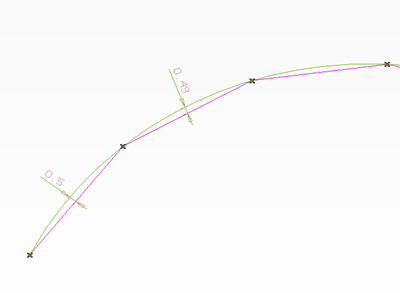
Discretization result for linear tolerance = 0.5mm (green : the exact surface (reference curve), red : resulting mesh). We can see that the maximum distance between the reference curve and the approximated mesh never exceeds 0.5.
To change the linear tolerance use
To disable linear tolerance use
Angular Tolerance
Angular tolerance is another way to control the resulting mesh precision.
It is the maximum angle between the reference curve (the brep curve stored in the body) and the approximated mesh. This tolerance has the advantage to be independant to the model size.
Angular tolerance represents deviation angle between points (green : exact surface definition, resulting triangle basis)
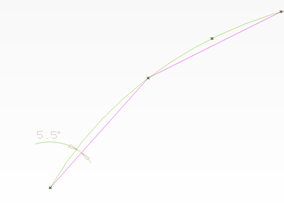
Discretization result for angular tolerance = 0.104rad (6deg) (green : the exact surface (reference curve), red : resulting mesh). We can see that the maximum angle between the reference curve and the approximated mesh never exceeds 6deg = 0.104rad.
To enable angular tolerance use
To disable angular tolerance use
By default, the linear tolerance is enabled alone.
The tolerance value is the second parameter of tess_InitTesselation(Dtk_string inWorkingDirectory,double inTolerance).
Both linear and angular modes can be combined. In such a case, final meshing results will depend on both criterias.
You can set the size ratio between two neighbor triangles with tess_set_Ratio(double tol) . A value at 1.0 generates only isosceles triangles
You can set the maximun lenght of a triangle with the function tess_set_MaxSize(double tol);
inmode can be :inratio is value limit to split face To get current status for this option use :
To disable the split method after use :
WARNING : this method is time-consuming and will be used for special part like turbine blades
Dtk_mesh into a Stl file with the following methods :dtkNoError tesselation is ready dtkTessellationNotStarted if tesselation not startedFor other information, do not hesitate to contact us.
After using one of the following tessellation methods :
tess_BodyToMeshes(const Dtk_BodyPtr& inBodyToWrite ,Dtk_tab<Dtk_mesh> & outMeshes,Dtk_tab<Dtk_Int32> & outIsSolid) tess_FaceToMesh(Dtk_FacePtr &inTabFace,Dtk_MeshPtr &outMesh) tess_ShellToMesh(const Dtk_ShellPtr &inShell, Dtk_MeshPtr &outMesh, Dtk_Int32 *outIsSolid) Dtk_mesh_face and Dtk_FacePtr and between Edge and mesh boundary with the following code : After using one of the following tessellation methods :
tess_FacesArrayToMesh(Dtk_tab<Dtk_FacePtr> &inTabFace,Dtk_MeshPtr &outMesh, Dtk_Int32 *outIsSolid) tess_FacesArrayToMesh()Dtk_mesh_face and Dtk_FacePtr only with the following code :