 |
DATAKIT SDK
V2026.3
|


|
|
DATAKIT SDK
V2026.3
|
|
Table Of Contents:
Before writing Jt files, you need to initialise Datakit API.
Checking the main, we need to :
stop Datakit API at the end with Dtk_API::StopAPI
The list of available tests of this sample are in function AllJtWTests
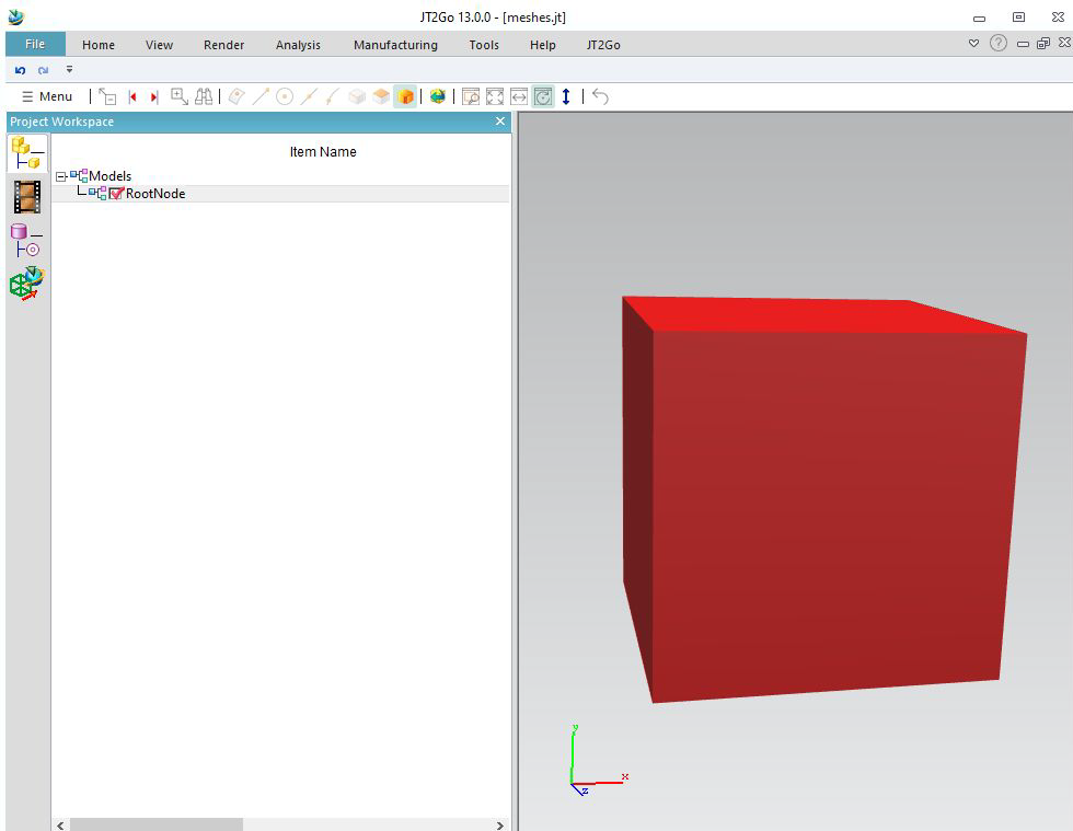
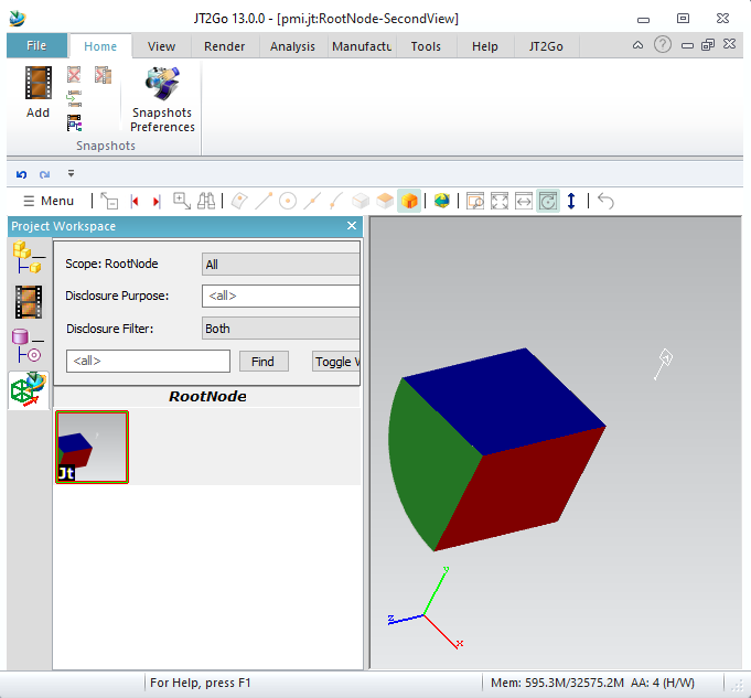
Let start with a simple code that will write a JT file containing a red cube (as mesh).
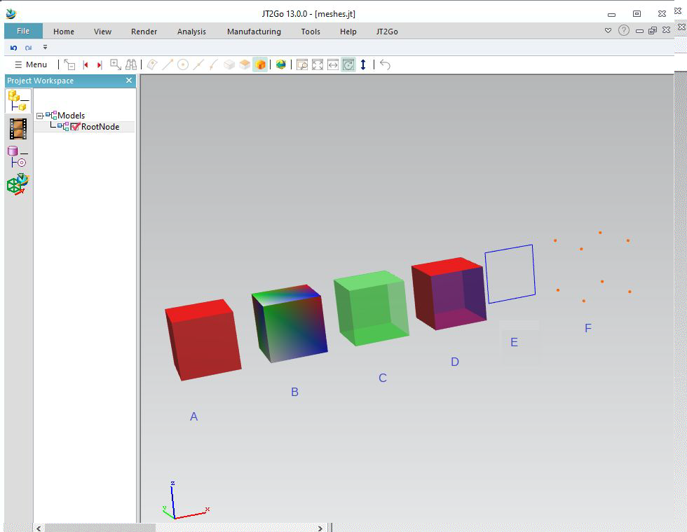
We will see with this example how to write transparency, wireframe, and points
This sample will make 6 cases :
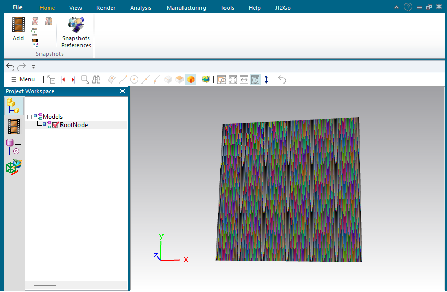
We will see in this sample how to set textures on meshes.
In this sample, we create a simple mesh, with only one quad, and with u,v textures coordinates. Setting a texture is made by setting a picture inside a Dtk_RenderInfosPtr. We link this renderinfo inside the info field of the mesh.
A Dtk_Picture can hold binary datas of each file formats (JPG, PNG....) or directly RGB pixels. In this case, we just create a RGB map, then we randomly set pixels inside. One the mesh embbed the texture, Datakit JT Writer apply it inside JTfiles.
Jt also support writing bodies as Parasolid bodies.
You will need to link Datakit Parasolid Write library.
Because Jt always stores meshes internally, you will need Datakit Tessellation library too.
Back to main, we see tessellation initialisation. From this sample, it will be required.
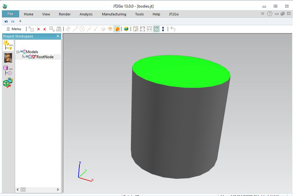
This sample initialises the tessellation, and writes a cylinder with a green face, and the others uncolored.
Then use function jtw_AddBody to write the body.
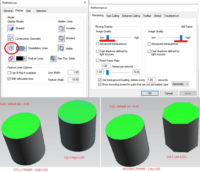
Datakit Jt Writer allows to write multiple level of details.
This example writes 2 bodies. The first one is like the previous sample. Tessellated with default linear tolerance as 0.005, see function tess_InitTessellation
Then we fill an array of LODS (0.001,-1) ; (0.01,-1) ; (0.1,-1) ;
The function jtw_AddBodyMultiLOD will tessellate 3 times at different tolerances.
We can add up to 9 LODS. Because tesselation takes 2 parameters, numbers of LODS will be sizeof array divided by 2.
A good way to see result is, inside JT2Go, to right click on the background, then :
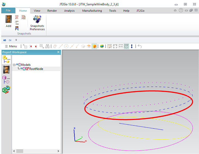
Fill a Dtk_Body with wire curves, and Datakit Jt Writer will write it as Wireframe segment as NURBS, and will also tessellate it as wire meshes.
We can set curve colors, thickness, and style filling info field of each curve
It is possible to hide a body. Just set blanked status on its info field. It also works with meshes.
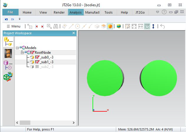
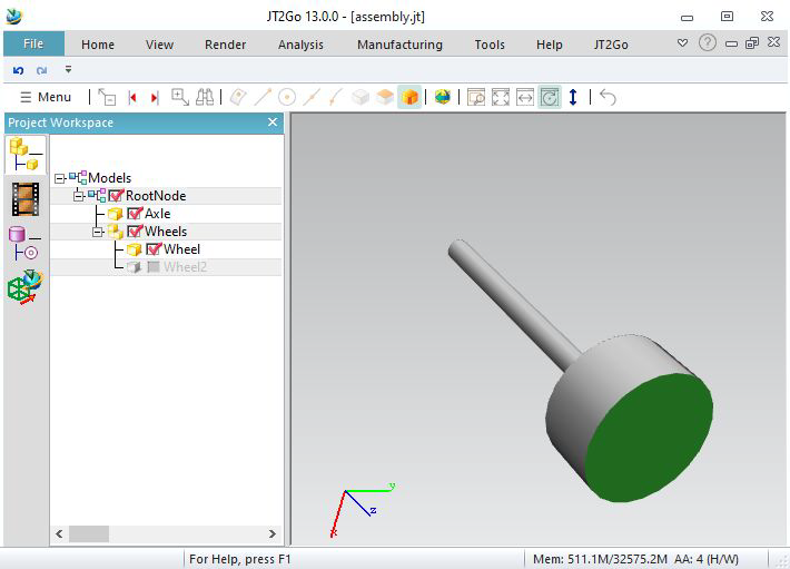
In our sample, we add 3 bodies on the same part. It is possible to see them in Jt2Go, by right
clicking into the project workshpace, enable « show leaf structure ».
Our bodies are considerated as « subnodes »
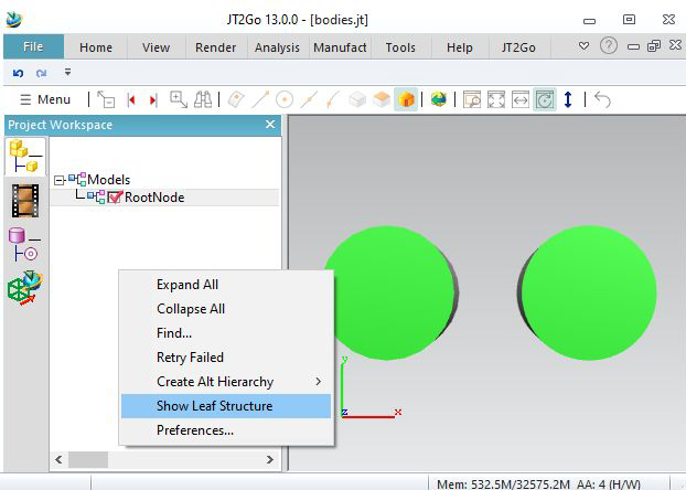
We see that the last body became invisible.
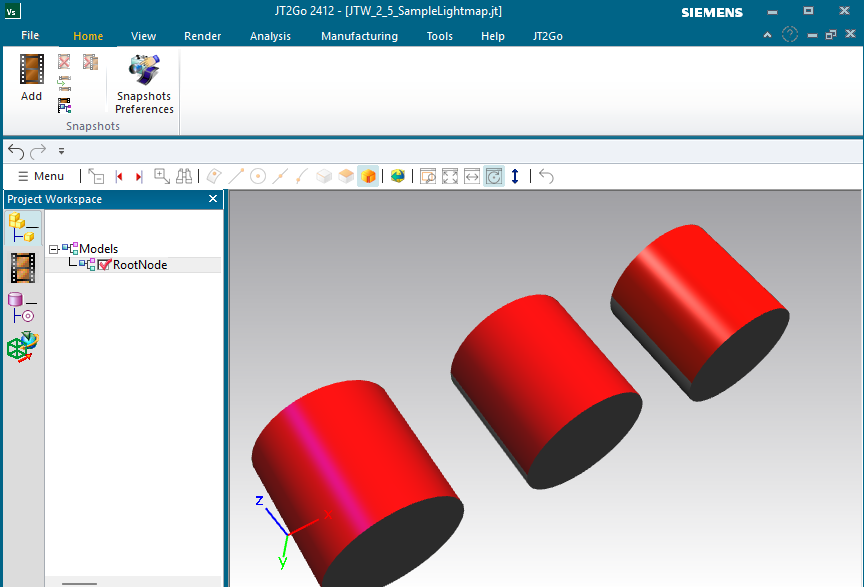
This sample allow to write lightmaps
Usually, we define colors using SetColor. But JT allows to set more parameters. So we can define a Dtk_LightmapPtr, and set it using Dtk_RenderInfoPtr, as you see in sample code.
We set in this sample the first face of each cylinder with different options. The first one has purple specular color, and no shininess. The second has no specular colors : it looks like matte and smooth. The last one has white specular color with shininess : it looks like brillant metal.
Note that you can combine Lightmap and textures (see section 1.3) into Dtk_RenderInfoPtr for meshes. (only meshes can hold textures).
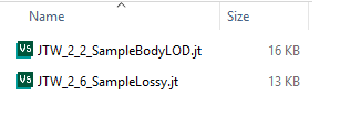
This sample allow to make internal lossy compression to save disk space
Let's get back on exemple 2.4. This one is almost the same : only an extra parameter has been added to function AddBody This is an optional parameter to define the lossy compression.
JT compress its datas internally. Meshes are made with a lot of floating point coordinates. These numbers have several digits, and storing all costs in compression. The lossy compression allows each point to be shifted to decrease the number of digts to store. The maximum shift allowed is the parameter given. So we understand that the default value of this parameter is 0.0 : means not shift anything at all, keeping a lossless compression.
Note that, contrary to LOD, the number of triangle is kept. Only the precision is affected. in our case 0.01 maximum for each point) It also affect normals.
This can be good for visualisation, but it should be avoided if you want to keep exact geometry.
On the result, we see this example is lighter than the LOD example. For big files, difference is more significant.
This parameter can be given to AddBody, and also AddMesh.
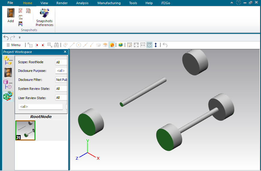
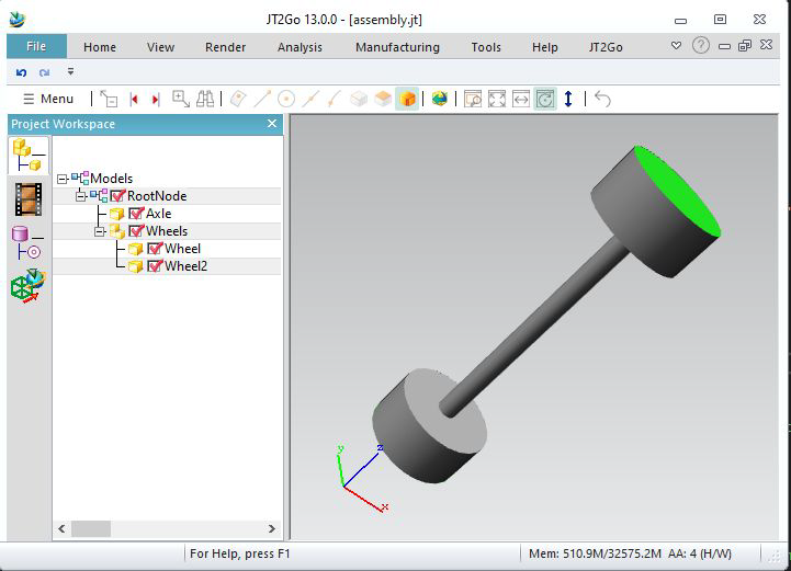
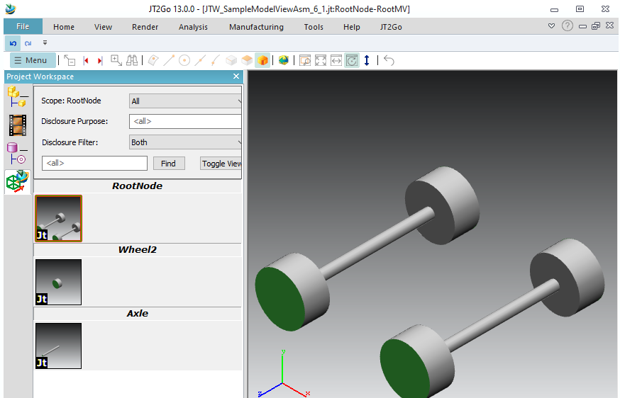
Here is an example to write an assembly, with sub assembly. No instances here, so « wheel » will be written twice in the file.
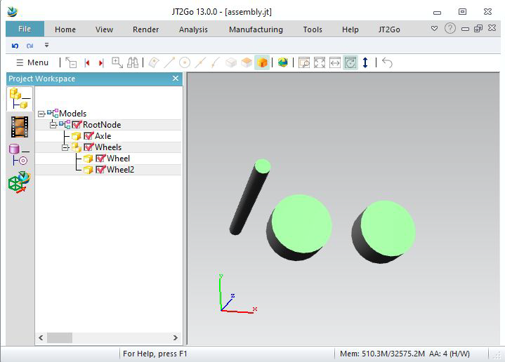
We can re-instantiate a part. The first time we call OpenInstance « Wheel », we give a custom ID for the part « wheel ». Here id_of_wheel, it needs to be a positive number.
Datakit JtWrite will store this ID, and when we call again OpenInstance with same ID, the writer automaticly re-instantiates the wheel. You must close the child.v
We provide a different Dtk_transfo (a placement matrix) for each instance, even a different name (wheel and wheel2) is possible.
This time, the wheel is stored once in the JT file.
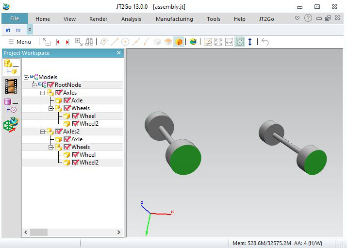
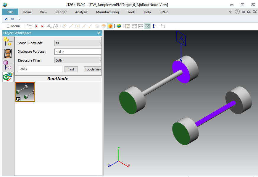
We can re-instantiate full subassembly. Here, we give an ID of 2 to Axles, and at the end we reuse it with another transformation.
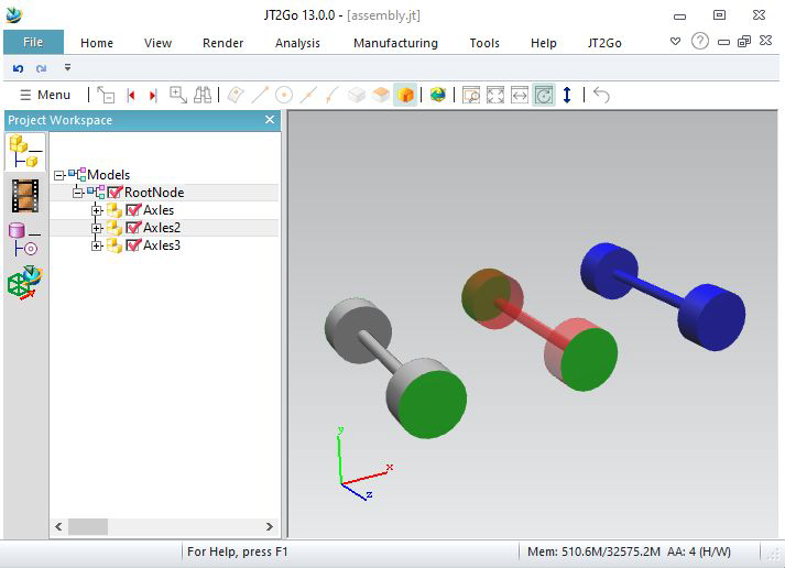
We can give colors to instances.
Let's take previous example.
Use LastInstance_SetInstanceColor to set colors on instances.
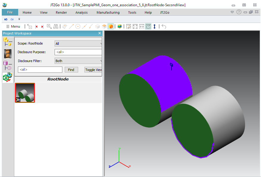
We re-instantiate Axles2 with a red color, and an alpha as 128 : transparency. But the last parameter "keepsubcolor" tells only uncolored colors are filled. (so green faces stay green)
For Axles3, we give a blue color, but the last parameter "overwritecolor" tells all is filled, even the green faces.
Get back to example 3.2.
Using LastInstance_SetInvisible will hide an instance.
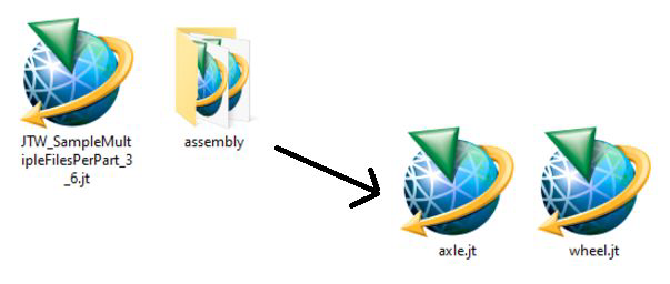
Jt allows to write multiple files.
Let's get the 3.3 example.
Here we call OpenInstance with « assembly/wheel.jt » and « assembly/axle.jt », it will write a new file for this part, into a new folder
(the main files name is «JTW_SampleMultipleFilesPerPart_3_6.jt » on this sample, seejtw_InitWrite).
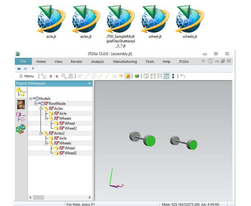
It is also possible to create JT files for each internal node :
We see a new JT file for each OpenInstance (that is neither re-instantiate nor the root)
Datakit JtWrite versions 8.0 ; 9.0 ; 9.1 ; 9.2 ; 9.3 ; 9.4 ; 9.5 ; 10.0 ; 10.1 ; 10.2 ; 10.3 ; 10.4 ; 10.5 ; 10.6 ; 10.7
We can choose the version to write in constructor. Default is version 9.5
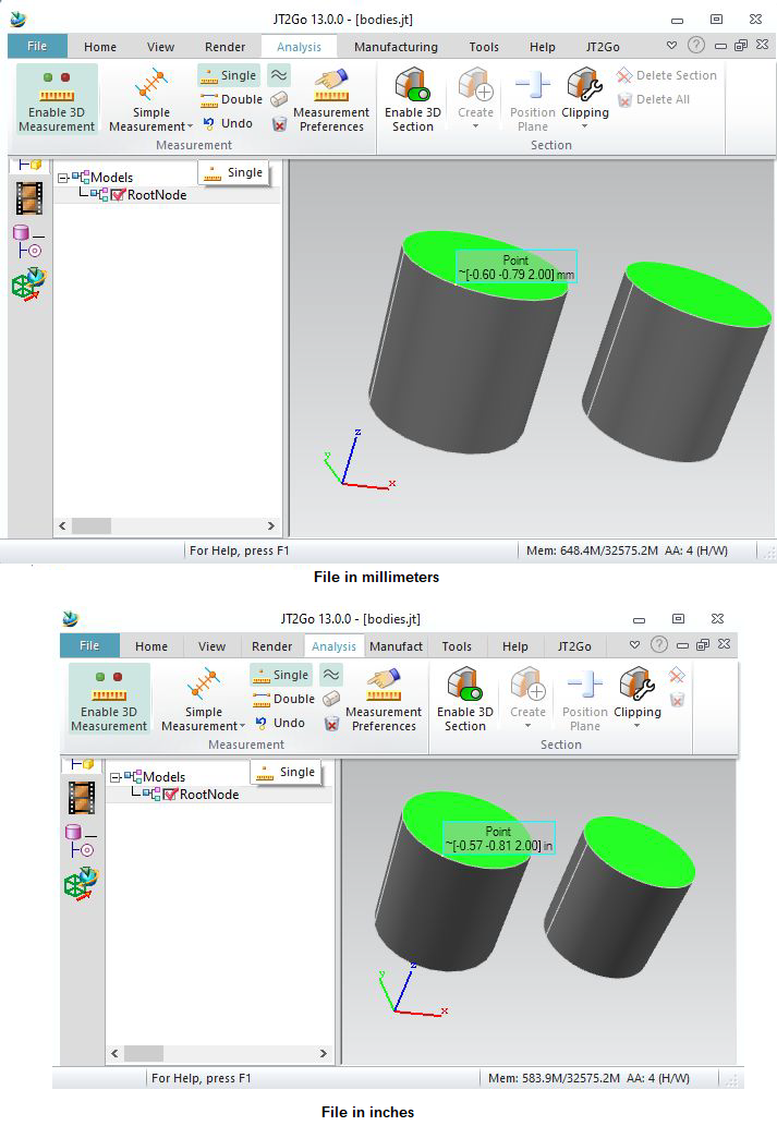
You can choose unit for your file.
Available units are millimeters, centimeters, meters, inches, feet, yards, micrometers, decimeters, kilometers, mils, miles. By default, units are millimeters
You can check this in Jt2Go using the Analysis menu, and make measurements
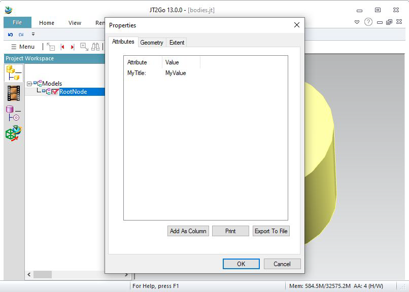
Metadatas can be written for each child. We can write several metadats for each child.
Here, we write « MyTitle » with « MyValue » for RootNode.
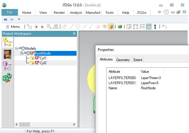
Fill layer of body info field (or mesh info field) to write layers on the corresponding node.
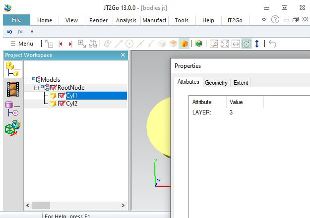
Here is a function to create a Dtk_LayerInfoSetPtr.
Just after the creation of RootNode, call AddLayerInfoSet. These datas are stored as properties into the RootNode.
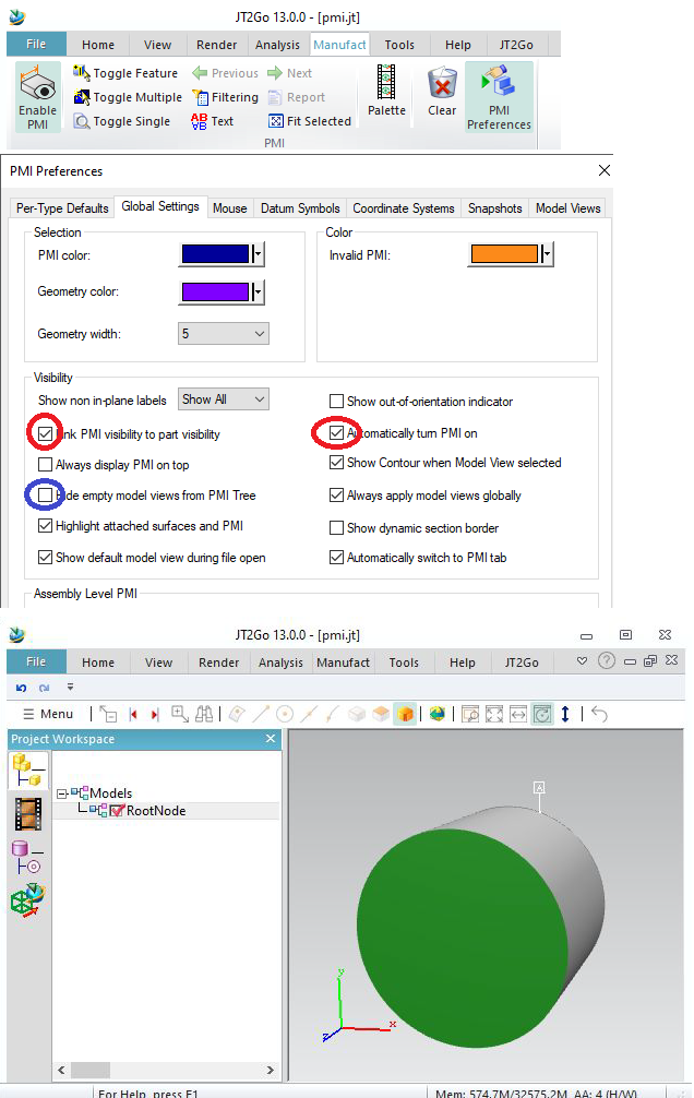
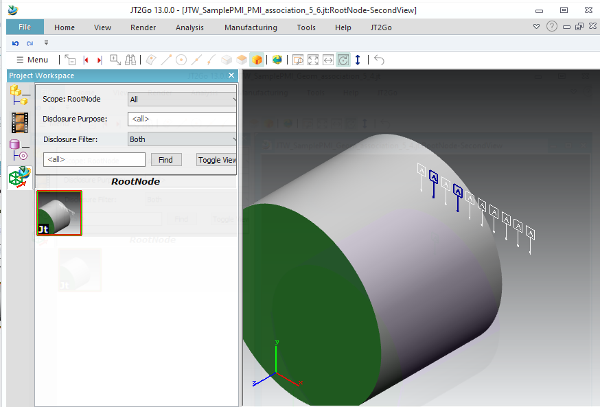
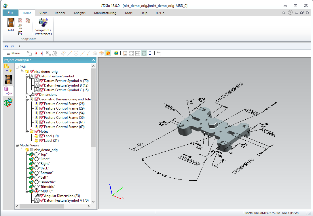
Datakit JT Writer allows to write PMI, using AddPMI
For this first example, the PMI is disconnected. Jt2Go wont show it by defaut. Lets configure it to show the PMI. Later, we can undo these modifications :
Go to PMI preference and make Jt2Go automatically turns on PMI. Do not hide empty modelview.
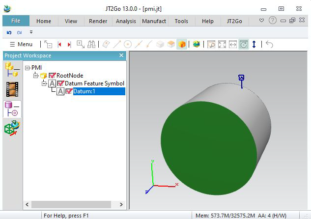
If you right click on the PMI and select « show in PMI tree », you will see the PMI type (a Datum Feature Symbol), and its name : « Datum:1 »
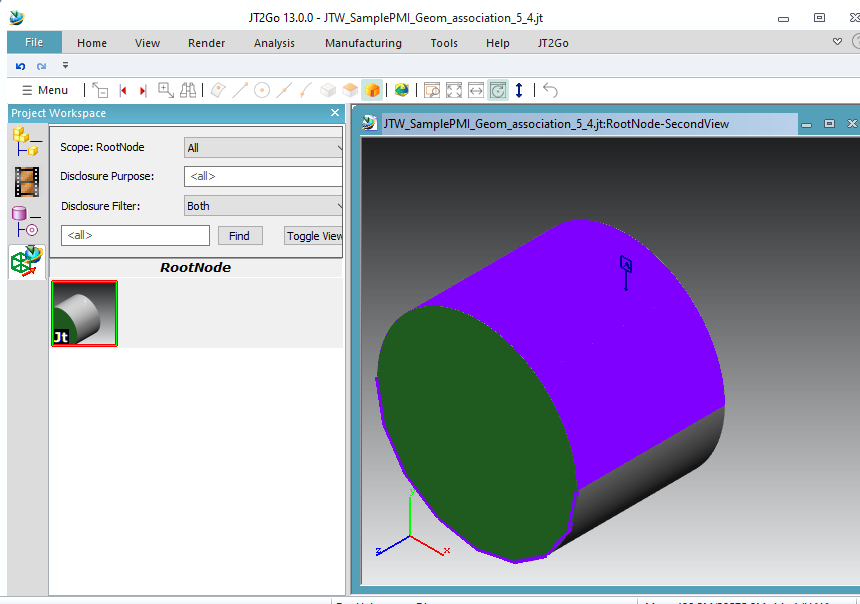
Datakit Jt Writer allows to write modelviews.
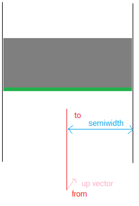
To define a Modelview, we need to define a camera.
Datakit JT Writer writes orthographic views.
So we need a point from, a point to, an up vector, and also a semiwidth. It it the distance between the targetpoint and the bound of screen.
In our example, the cylinder has a radius of 100, so the semiwidth is 100, we transmit it in Camera construction for « FitView ».
As we see, we also fill Modelview names in info field.
(We suggest to write version 9.5 for better result).
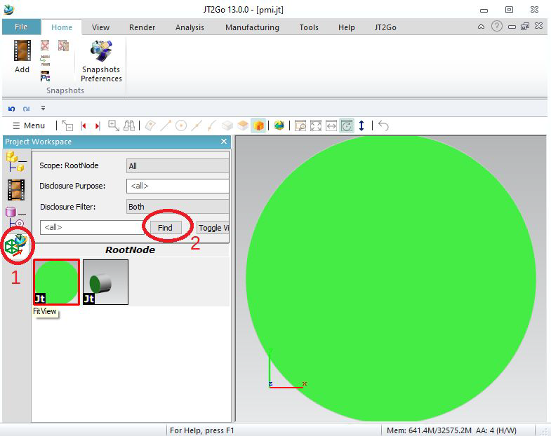
Here is the result in Jt2Go.
To see Modelviews, click on Modelviews on the left, then « find » to compute modelviews.
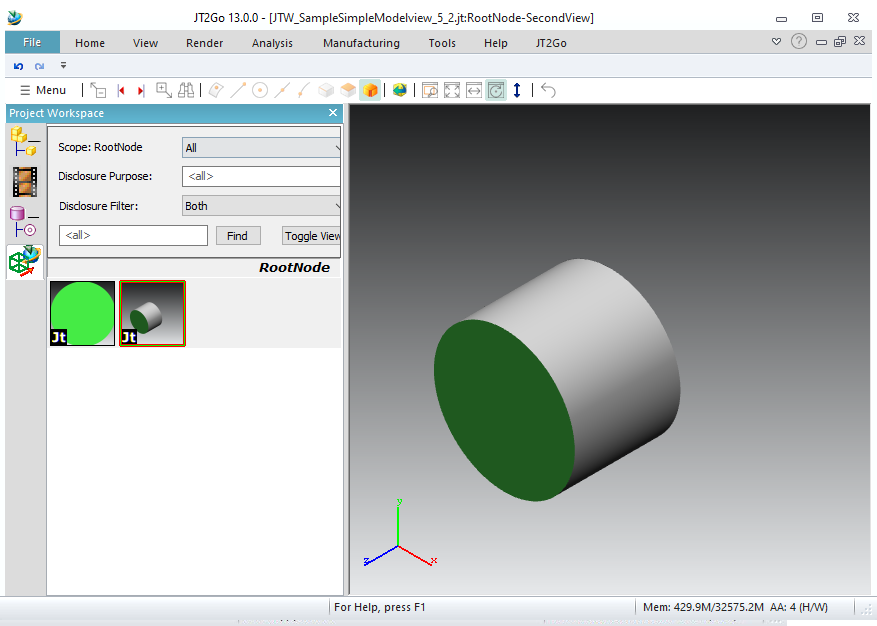
Selecting a modelview will set the camera.
You can see the name of the modelview when highlighting the view.
As you see, the PMI is not present in the modelview. We will have to associate it.
To insert a PMI into the modelview, you have to give an ID to the PMI (here we give for example ID 5), an ID to the PMI (here for example ID 8), and use ConnectPMI_ModelViews.
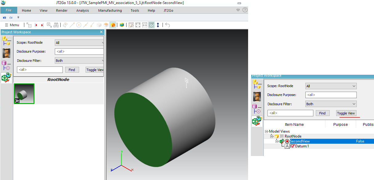
Selecting « toggle view » will show which PMI are in which views.
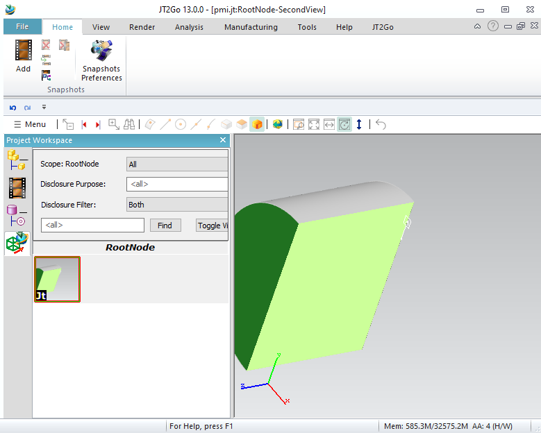
We can associate a PMI to geometry (face, edge or vertex)
The body cylinder has face ID from 1 to 4, and edge ID from 11 to 16.
Here we associate the PMI 5 to face number 2, and edge number 15.
Clicking on PMI will highlight the face and the edge in JT2Go.
It is also possible to write sections, giving second parameter of Dtk_ModelDisplay constructor.
Here we give just a plane, and the section cuts the model in this modeldisplay. Default cutting color is yellow/green
It is also possible to make multiple sections. You need to fill a body to give to Dtk_ModelDisplay constructor.
In this function, we fill a Dtk_Entity as Body, containing 2 planes. These planes are colored (red and blue) to give section colors.
Enable MakeMultiSection function in this code (B) (disable (A)) to see this result :
It is possible to link some PMI together. Here we create 10 PMI (ID 5 to 14) and we connect PMI 6 to PMI 8 with function ConnectPMI_PMI.
(Note that I changed Modelview ID to 30, to not collide with a PMI ID)
Selecting this PMI will automaticly select the other.
It is possible to write Axis Systems, reference planes, reference axis and reference points.
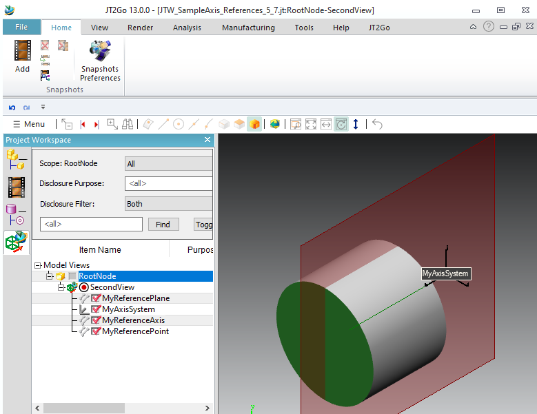
If you add more than one body in a single node, and want to connect a PMI on a specific body, you need another parameter. This example sets Id 10 and 11 to cylinders. Then the ConnectPMI_Geom sets the last parameter, to target face 2 in body 10, and also edge 15 on body 11.
A lot of types of PMI are supported. It is written as wireframe.
You can make modelviews in each node you want, by default the modelviews target all subassembly where the modelview is added.
Note that for this example, modelviews are empty, you need to tell Jt2Go to show empty modelviews (see 5.1.)
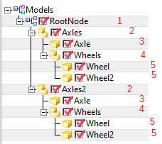
Before targeting a specific instance, we need to give ID to each node :
Let's see this code :
With this code, we give an ID to each node, into OpenInstance, we see ("Axles", 2), ("Axle", 3), ("Wheels", 4), ("Wheel", 5)
Some are re-instantiated (2 and 5)
It gives this tree inside Jt2Go
With this, we can target a node. But there are multiple nodes « 5 » and multiple nodes « 2 », because these nodes are re-instantiated.
To remove ambiguity, we can give ID to instances too, using LastInstance_SetInstanceID :
In this code, we define instancesid 11,12,13,14,15,16. (Avoid giving same id as idParts given by OpenInstance)
Now, the tree is :
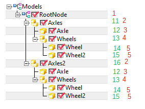
Now we can reach an instance, using a « route » to reach it :
To reach first wheel, route is 1,11,2,13,4,14,5
To reach second Axle, route is 1,16,2,12,3
To reach last Wheels subassembly, route is 1,16,2,13,4
Now lets fill function MakePmiOnRoot (with option 1 for this sample) to target only an axle, and just a wheel on the other axle :
Fill a « route » to target an assembly you need.
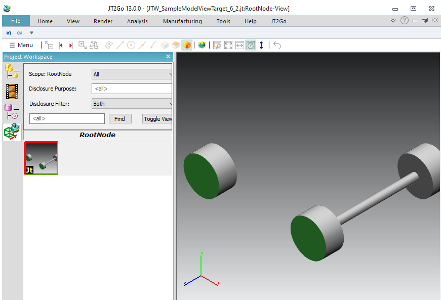
The previous sample shows how to select subassemblies to put in modeldisplay.
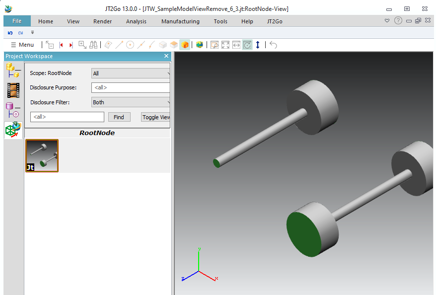
We can select subassemblies to remove from modeldisplay
See previous code with option 2 for this sample.
We consider route 1,11,2,13,4,14 (to a specific wheel), then we use last parameter "hide" of ConnectModelView_Instance to hide it.
In the previous example we selected instances to add, now we keep all instances besides the selected one.
Lets consider a PMI into root node, we want it to target a face of a specific geometry instance, and also another face somewhere else in assembly.
See previous code with option 3 for this sample.
This sample shows how to make an exploded view
See previous code with option 4 for this sample.
We use the last parameter of ConnectModelView_Instance, a pointer on a Dtk_Transfo that override the position of each component, in world system coordinates. We need to connect to the modelview each instances, with a transformation matrix. We define the full route of each part (inluding instances). Only 2 wheels of this sample have their position redefined.